
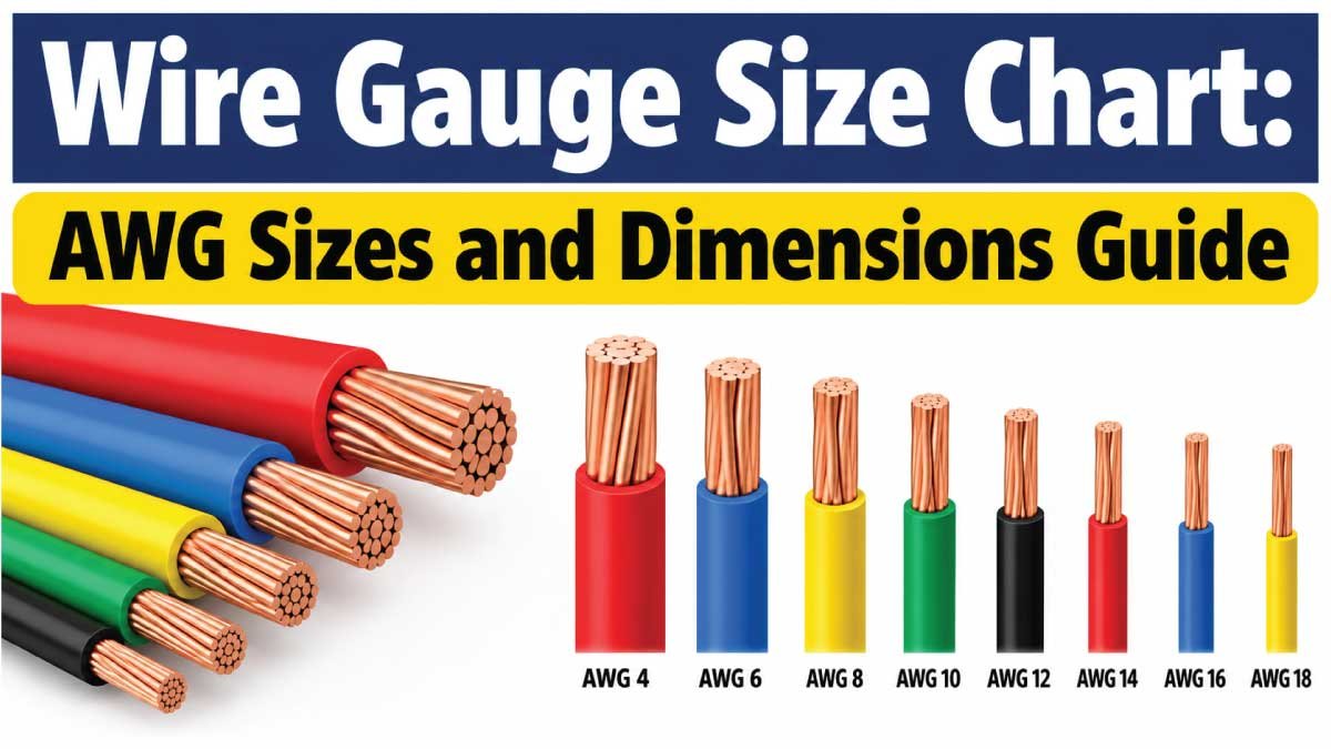
Choosing the correct wire gauge is essential for electrical safety, reliable performance, and efficient current flow. Whether you are wiring a home, installing automotive accessories, building electronic projects, or selecting cables for industrial equipment, understanding wire gauge sizes helps you choose a conductor that meets the requirements of your application.
The American Wire Gauge (AWG) system is widely used to identify the diameter of electrical conductors in North America. It assigns a number to each standard wire size, with smaller gauge numbers representing thicker wires and larger gauge numbers representing thinner wires. For example, 10 AWG wire is thicker than 14 AWG wire.
A wire gauge size chart makes it easier to compare wire diameters, cross-sectional areas, and typical applications. However, choosing the right wire involves more than measuring its thickness. Current capacity, wire length, voltage drop, insulation temperature rating, conductor material, and installation conditions also matter.
This guide explains AWG sizes, wire dimensions, common gauge measurements, electrical applications, and practical tips for selecting the right wire.
What Is a Wire Gauge Size Chart?
A wire gauge size chart is a reference table that shows the dimensions associated with different wire sizes. For electrical wiring, the chart commonly includes the AWG number, conductor diameter, cross-sectional area, and sometimes approximate resistance.
These measurements help electricians, engineers, technicians, and DIY users compare conductors before selecting wire for a particular project.
What Does AWG Mean?
AWG stands for American Wire Gauge. It is a standardized system for identifying the diameter of solid, round electrical conductors.
The system follows an inverse relationship between gauge number and conductor size:
- Smaller AWG number: Thicker conductor with a larger cross-sectional area.
- Larger AWG number: Thinner conductor with a smaller cross-sectional area.
For example, 8 AWG wire is thicker than 12 AWG wire, while 16 AWG wire is thinner than both.
This relationship can seem counterintuitive at first, but remembering that lower gauge numbers indicate thicker wire makes AWG charts easier to understand.
Why Wire Gauge Matters
Wire gauge affects electrical resistance, voltage drop, heat generation, and the amount of current a conductor can safely carry under specified conditions.
A conductor that is too small for its load may experience excessive heating or voltage drop. A correctly selected conductor helps the electrical system operate reliably and reduces the risk of overheating.
However, wire gauge alone does not determine safe current capacity. Insulation type, ambient temperature, installation method, conductor material, bundling, and applicable electrical codes must also be considered.
AWG Wire Gauge Size Chart: Common Wire Dimensions
The following chart lists common AWG sizes and their approximate conductor dimensions. The diameter values refer to the bare conductor rather than the complete insulated wire.
| AWG Size | Diameter (inches) | Diameter (mm) | Cross-Sectional Area (mm²) | Typical Uses |
|---|---|---|---|---|
| 4/0 (0000) | 0.4600 | 11.684 | 107.2 | Large electrical conductors |
| 3/0 (000) | 0.4096 | 10.405 | 85.0 | High-current installations |
| 2/0 (00) | 0.3648 | 9.266 | 67.4 | Large power conductors |
| 1/0 (0) | 0.3249 | 8.251 | 53.5 | Heavy electrical applications |
| 1 AWG | 0.2893 | 7.348 | 42.4 | Large feeders and equipment |
| 2 AWG | 0.2576 | 6.544 | 33.6 | Power distribution |
| 4 AWG | 0.2043 | 5.189 | 21.2 | Heavy-duty wiring |
| 6 AWG | 0.1620 | 4.115 | 13.3 | Selected high-current circuits |
| 8 AWG | 0.1285 | 3.264 | 8.37 | Equipment and power circuits |
| 10 AWG | 0.1019 | 2.588 | 5.26 | Selected branch circuits |
| 12 AWG | 0.0808 | 2.053 | 3.31 | General-purpose branch wiring |
| 14 AWG | 0.0641 | 1.628 | 2.08 | Lighting and other suitable circuits |
| 16 AWG | 0.0508 | 1.291 | 1.31 | Electronics and light-duty wiring |
| 18 AWG | 0.0403 | 1.024 | 0.823 | Control and low-power wiring |
| 20 AWG | 0.0320 | 0.812 | 0.518 | Electronics and signal wiring |
| 22 AWG | 0.0253 | 0.644 | 0.326 | Low-current signals |
| 24 AWG | 0.0201 | 0.511 | 0.205 | Data and electronic circuits |
| 26 AWG | 0.0159 | 0.405 | 0.129 | Fine electronic wiring |
| 28 AWG | 0.0126 | 0.321 | 0.081 | Small signal conductors |
| 30 AWG | 0.0100 | 0.255 | 0.051 | Fine electronics and small connections |
The dimensions are approximate standard AWG values. Actual finished wire dimensions may vary according to conductor construction and manufacturing tolerances.
How to Read the AWG Chart
Consider 12 AWG wire. Its bare conductor diameter is approximately 2.053 mm, and its cross-sectional area is about 3.31 mm².
A 10 AWG conductor is thicker, with a diameter of approximately 2.588 mm and a cross-sectional area of about 5.26 mm². This larger cross-sectional area generally means lower electrical resistance per unit length when comparing conductors of the same material.
The chart helps you compare physical dimensions, but it should not be used by itself to determine the maximum safe current for a circuit.
What Do 1/0, 2/0, 3/0, and 4/0 Mean?
Large AWG sizes use a notation that differs from ordinary numbered gauges. These sizes are written as 1/0, 2/0, 3/0, and 4/0, and are commonly spoken as “one-aught,” “two-aught,” and so on.
The sequence becomes thicker as the number of zeros increases. A 4/0 conductor is larger than 3/0, 2/0, and 1/0 wire.
These sizes are used in some large power, battery, and distribution applications, depending on the electrical design.
AWG Wire Diameter Chart in Millimeters
For projects that use metric measurements, converting AWG diameters into millimeters makes comparison easier.
| AWG Size | Bare Diameter (mm) | Cross-Sectional Area (mm²) |
|---|---|---|
| 6 AWG | 4.115 | 13.30 |
| 8 AWG | 3.264 | 8.37 |
| 10 AWG | 2.588 | 5.26 |
| 12 AWG | 2.053 | 3.31 |
| 14 AWG | 1.628 | 2.08 |
| 16 AWG | 1.291 | 1.31 |
| 18 AWG | 1.024 | 0.823 |
| 20 AWG | 0.812 | 0.518 |
| 22 AWG | 0.644 | 0.326 |
| 24 AWG | 0.511 | 0.205 |
| 26 AWG | 0.405 | 0.129 |
| 28 AWG | 0.321 | 0.081 |
| 30 AWG | 0.255 | 0.051 |
AWG and Metric Wire Sizes Are Not Always Exact Matches
Metric wire sizes are often identified by cross-sectional area in square millimeters, such as 1.5 mm², 2.5 mm², 4 mm², or 6 mm². AWG, by contrast, identifies a standardized conductor diameter.
Because these systems use different nominal size steps, a metric conductor does not always have an exact AWG equivalent.
For example, 2.5 mm² metric wire has a cross-sectional area between common 14 AWG and 12 AWG values. The closest nominal area does not automatically establish electrical equivalence or interchangeability.
When replacing a conductor, check the required current capacity, resistance, insulation, installation conditions, and applicable standards rather than relying only on a conversion chart.
Wire Gauge and Current Capacity
One of the most common reasons people consult an AWG wire gauge chart is to determine which wire can carry a particular electrical current.
Current capacity, often called ampacity, describes the current a conductor can carry under specified conditions without exceeding its permitted temperature limits.
Although thicker conductors generally have lower resistance and can often carry more current, there is no single universal ampacity for every AWG size.
Factors That Affect Wire Ampacity
Several factors influence the safe current capacity of an electrical conductor.
Conductor material: Copper and aluminum have different electrical resistance and installation requirements.
Insulation rating: The insulation must be suitable for the expected operating temperature and environment.
Ambient temperature: Hotter surroundings can reduce the current a conductor is permitted to carry.
Installation method: Conductors installed in conduit, cable assemblies, open air, or thermal insulation may have different ratings.
Number of loaded conductors: Grouping multiple current-carrying conductors can increase heat buildup and require ampacity adjustments.
Terminal ratings: Connected equipment and terminals may impose lower temperature or current limits.
For these reasons, an AWG diameter chart should not replace an electrical ampacity table or a calculation based on the applicable electrical code.
Common Wire Sizes and Typical Uses
The following examples describe applications where certain gauges may be encountered. They are not universal current ratings or instructions for selecting a conductor for a particular load.
| AWG Size | Common Application Examples |
|---|---|
| 4–6 AWG | Selected large feeders, equipment, and battery conductors |
| 8 AWG | Certain power circuits and equipment connections |
| 10 AWG | Some branch circuits and higher-load equipment |
| 12 AWG | General-purpose wiring in appropriately rated installations |
| 14 AWG | Lighting and other permitted branch-circuit applications |
| 16–18 AWG | Control circuits, appliances, and suitable low-power wiring |
| 20–24 AWG | Electronic devices, sensors, and signal circuits |
| 26–30 AWG | Fine electronic connections and low-current signals |
The correct size for any specific application must be established using the load current, circuit protection, conductor material, insulation rating, installation conditions, and applicable code.
Also Read:’
How to Choose the Correct Wire Gauge
Choosing a wire gauge involves more than identifying the diameter. Follow a systematic approach to select a conductor that meets the electrical and physical requirements of your project.
1. Determine the Load Current
Identify the current the circuit is expected to carry. For a known electrical load, the equipment nameplate or manufacturer documentation may provide the necessary information.
For some loads, the starting current or continuous operating requirements must also be considered. Use the applicable electrical design method to determine the conductor size.
2. Measure the Circuit Length
Longer wire runs create greater resistance and can produce more voltage drop. This is especially important in low-voltage systems, where a small voltage reduction may represent a substantial percentage of the supply voltage.
Consider the complete electrical path. In a typical two-conductor DC circuit, current travels through both the outgoing and return conductors, so both lengths contribute to voltage drop.
3. Consider Voltage Drop
Voltage drop is the reduction in voltage caused by current flowing through the resistance of a conductor.
For a simple resistive conductor, the relationship is described by Ohm’s law:
[
V = I \times R
]
Here, (V) is voltage drop, (I) is current, and (R) is resistance.
Increasing conductor cross-sectional area generally reduces resistance and can help limit voltage drop. However, acceptable voltage drop depends on the circuit, equipment requirements, and applicable design standards.
4. Select the Conductor Material
Copper and aluminum are not interchangeable on a size-for-size basis without considering their different electrical and mechanical properties.
If using aluminum conductors, ensure that the conductor, terminals, connectors, and installation method are specifically approved for aluminum. Follow the manufacturer’s instructions and applicable code requirements.
5. Check the Insulation and Environment
Wire insulation must be suitable for the operating temperature, moisture exposure, chemicals, sunlight, and mechanical conditions expected in service.
A bare conductor diameter does not include insulation thickness. If the wire must fit inside a connector, enclosure, conduit, or cable gland, check the finished outside diameter as well.
6. Confirm Circuit Protection and Code Requirements
The conductor must be protected against overcurrent in accordance with the applicable electrical code. The selected breaker or fuse, conductor ampacity, equipment terminals, and installation method must be compatible.
For mains wiring, building installations, and other safety-critical work, use a qualified electrician when required and follow local regulations.
Also Read:’
Solid Wire vs. Stranded Wire Gauge
AWG sizes can identify both solid and stranded conductors, but their physical construction differs.
Solid Wire
Solid wire consists of a single conductor. It is often used in fixed installations and some electronic applications where the conductor will not experience frequent movement.
Because it has a single solid core, its physical diameter can be measured directly when the conductor is accessible.
Stranded Wire
Stranded wire consists of multiple smaller wires grouped together. It is often used where flexibility is important, such as equipment connections, automotive wiring, and movable assemblies.
The overall bundle diameter may be larger than the equivalent solid conductor diameter because of spaces between strands and the way the strands are arranged.
The AWG designation generally refers to the conductor’s standardized size, not the complete insulated wire’s outside diameter. When selecting terminals or connectors, follow the manufacturer’s specified conductor range and construction requirements.
Also Read:’
Common Wire Gauge Measurement Mistakes
Measuring the Insulation Instead of the Conductor
The insulation increases the overall diameter of the wire. To identify AWG by diameter, measure the bare conductor, not the outside of the insulation.
For stranded wire, use the cable specification or an appropriate measurement method rather than assuming the bundle diameter equals the solid-wire diameter.
Assuming Lower AWG Means Less Wire
The AWG numbering system runs in the opposite direction from what some people expect. A lower number indicates a thicker conductor, while a higher number indicates a thinner one.
Using Diameter Alone to Choose Wire
Diameter helps identify the gauge, but it does not establish safe ampacity. Temperature ratings, installation conditions, conductor material, and circuit protection must also be considered.
Ignoring Voltage Drop
A conductor may satisfy a basic ampacity requirement but still create excessive voltage drop over a long distance. Evaluate both ampacity and voltage drop when designing a circuit.
Treating Metric and AWG Sizes as Identical
Metric cross-sectional areas and AWG designations do not always correspond exactly. Verify the specifications required by the application before substituting one size for another.
Frequently Asked Questions About Wire Gauge Sizes
What Does AWG Stand For?
AWG stands for American Wire Gauge. It is a standardized system used to identify the diameter of electrical conductors, particularly in North America.
Is 12 AWG Wire Thicker Than 14 AWG Wire?
Yes. A 12 AWG conductor has a larger diameter and cross-sectional area than a 14 AWG conductor. The lower gauge number represents the thicker wire.
What Is the Diameter of 10 AWG Wire?
The nominal bare conductor diameter of 10 AWG wire is approximately 0.1019 inches, or 2.588 millimeters. The finished outside diameter will be larger when insulation is included.
What Is the Difference Between Wire Gauge and Cross-Sectional Area?
Wire gauge is a standardized size designation, while cross-sectional area measures the conductor’s area, typically in square millimeters. Cross-sectional area helps describe how much conductive material is present and is useful when comparing electrical resistance.
Can I Use a Larger AWG Number for a High-Current Circuit?
A larger AWG number means a thinner conductor, which generally has greater resistance per unit length for the same material. Do not increase the gauge number without verifying that the conductor meets the circuit’s ampacity and voltage-drop requirements.
Does Stranded Wire Have a Different AWG Size From Solid Wire?
AWG identifies the conductor size, but stranded and solid wires have different physical constructions. A stranded wire bundle may have a larger overall diameter because of the spaces between individual strands.
How Do I Convert AWG to Millimeters?
Use an AWG diameter chart to find the nominal bare conductor diameter in millimeters. If you need to compare metric wire, check its cross-sectional area as well, because a metric size and an AWG size may not match exactly.
Conclusion
A wire gauge size chart helps you compare AWG numbers, conductor diameters, and cross-sectional areas. The key rule is simple: smaller AWG numbers represent thicker wires, while larger numbers represent thinner conductors.
However, choosing the right wire requires more than matching a diameter. Consider current demand, circuit length, voltage drop, insulation rating, conductor material, installation conditions, and the applicable electrical code.
Use the chart as a starting point, then verify the required ampacity and voltage-drop performance for your specific application. Correct wire selection helps support reliable electrical operation and reduces the risk of overheating, excessive voltage loss, and unsafe installations.
